Page 6 of 39
Project: Slideways z26
Posted: Wed Dec 07, 2011 10:34 pm
by Barry

Passenger side shock tower coming together. Need to finish welding and do some sheet metal work to tie it into the fender well.
Re: Project: Slideways z26
Posted: Thu Dec 08, 2011 9:42 am
by 3X00-Modified
Please tell me your going to reinforce the outer side of that shock tower... If you ask me its way too much just hanging out there and I think it might bend under heavy load.
Project: Slideways z26
Posted: Thu Dec 08, 2011 10:13 am
by Barry
Barry wrote:Need to finish welding and do some sheet metal work to tie it into the fender well.
Re: Project: Slideways z26
Posted: Thu Dec 08, 2011 12:32 pm
by keoki1978
Got a question bout how you mounted the 240 rear subframe in. Did you set it to be parallel to the ground so that the drive shaft would be straight? Looking at an S13 in the yard the other day, looks as if it would be parallel if the car was on a flat surface with wheels on it. Also, the front 2 mounting points you did, I couldn't tell by the pics, how did you do that one?? Cut the factory mounting points off the beretta, then what? Other than that, looks great.
Re: Project: Slideways z26
Posted: Thu Dec 08, 2011 1:13 pm
by 3X00-Modified
Barry wrote:Need to finish welding and do some sheet metal work to tie it into the fender well.
I'm thinking a bit more robust than sheetmetal work though.
Re: Project: Slideways z26
Posted: Thu Dec 08, 2011 1:28 pm
by Barry
keoki1978 wrote:Got a question bout how you mounted the 240 rear subframe in. Did you set it to be parallel to the ground so that the drive shaft would be straight? Looking at an S13 in the yard the other day, looks as if it would be parallel if the car was on a flat surface with wheels on it. Also, the front 2 mounting points you did, I couldn't tell by the pics, how did you do that one?? Cut the factory mounting points off the beretta, then what? Other than that, looks great.
It's at just about the same angle as a Nissan. Haven't bolted a diff up yet to check driveshaft angle but it should be very close.
For the front mounts I cut the stock mounts off. Then built a 3 sided "box" with a bolt through the bottom for the mount.
Re: Project: Slideways z26
Posted: Thu Dec 08, 2011 1:30 pm
by Barry
3X00-Modified wrote:Barry wrote:Need to finish welding and do some sheet metal work to tie it into the fender well.
I'm thinking a bit more robust than sheetmetal work though.
I think it will be plenty. The stock Nissan towers are sheet metal, most unibody cars are. The supports you see there will take a significant ammmout of the load but I already watch them flex with just a floor jack. Once the shock tower becomes the third member I think it will be stronger than oem Nissan
Re: Project: Slideways z26
Posted: Thu Dec 08, 2011 2:16 pm
by keoki1978
How soon do you think you'll have it done?? Have you started on the front end?
I picked up the S13 rear this past sunday, I got my brothers T5 from a stang, and I plan to try and use the S13/S14 front subframe and rack. Plan to use my 3100 for now but might look into a LS1. I'm getting all the hard parts ready. BTW, I've got a 95 GAGT 2 door that I will be doing this to.
Keep the updates coming.
Re: Project: Slideways z26
Posted: Thu Dec 08, 2011 3:58 pm
by Barry
Hopefully in a week rear will be done. Then I just need brake lines, ebrake cables, and fuel system.
A 3100 will likely not fit under your hood, I measured it when I still had my s13. The cross member is too close to the hood. A modded oil pan would probably do the trick
Ls1 would fit better, assuming no shock tower issues.
Re: Project: Slideways z26
Posted: Thu Dec 08, 2011 4:37 pm
by keoki1978
I hear you. What front cross member do you plan to use? What engine?
Re: Project: Slideways z26
Posted: Thu Dec 08, 2011 6:45 pm
by Barry
Im keeping beretta subframes and control arms. Then using bigger GM car knuckles and hubs. There aluminum and the hubs are 5x115. They steer from the knuckle, so I will run the left knuckle on the right side of the car and vice versa. The e36 bmw has a forward mounted steering rack, so I will use that. Im hoping it will land in front of the engine and not under it. I will put braces between the stock frames to make them one piece and will also be mounting the engine to them.
Im using my 3500 v6 that is currently in there.
A FWD 660 is tall as hell. With a conventional crossmember like a 240, it wont fit under the hood.
Re: Project: Slideways z26
Posted: Thu Dec 08, 2011 8:43 pm
by Alpinestar10
Dude sorry buy that crap looks like its going to twist the first time you try to drift it i by no means am an engineer or anything but why not box rectangular crap instead of that opend up stuff? is it atleast think? it looks like its 18 gauge?
Re: Project: Slideways z26
Posted: Thu Dec 08, 2011 8:53 pm
by DTMAce
Alpinestar10 wrote:Dude sorry buy that crap looks like its going to twist the first time you try to drift it i by no means am an engineer or anything but why not box rectangular crap instead of that opend up stuff? is it atleast think? it looks like its 18 gauge?
Barry wrote:3X00-Modified wrote:Barry wrote:Need to finish welding and do some sheet metal work to tie it into the fender well.
I'm thinking a bit more robust than sheetmetal work though.
I think it will be plenty. The stock Nissan towers are sheet metal, most unibody cars are. The supports you see there will take a significant ammmout of the load but I already watch them flex with just a floor jack. Once the shock tower becomes the third member I think it will be stronger than oem Nissan
Because people just can't seem to be able to read... LOL Sorry man, couldn't help it...

He plans to do more to the tower, including boxing them in..

Re: Project: Slideways z26
Posted: Thu Dec 08, 2011 9:10 pm
by Alpinestar10
not talking about the towers i mean the actual cross member.
Re: Project: Slideways z26
Posted: Fri Dec 09, 2011 10:10 am
by 3X00-Modified
Barry wrote: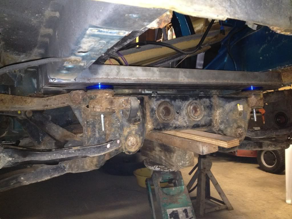
It looks like he U channeled a 2x3 steel box tube, It's not 18 gauge, its more like 1/8" thick... But I do feel that some of the structure is a bit weak looking, but there is no way to test that until it gets sideways, OR he designs the whole thing in solidworks and force tests it... And I know he doesn't have the time to do that, so he's working with what he has. Thing's may change after its done but only time will tell.